


95% d’économie d’eau - Tour de refroidissement 100
-
Prix public : 29 500,00€
- H.T : 29 500,00€
- Disponibilité : Demander un Devis
- FICHE PRODUIT

SPECIFICATIONS TECHNIQUES
Alimentation électrique monophasé: 230V/50Hz/1Ph
Dimensions (Largeur Profondeur Hauteur): 900-1810-2120 mm
Poids vide: 180 kg Poids en utilisation: 400 kg
Code douanier: -
UNE TOUR DE REFROIDISSEMENT VERT
Ne pas gaspiller l’eau signifie ne pas appauvrir les ressources hydriques et économiser de manière significative en termes de coût d’exploitation.
Cette tour d’évaporation économise 95% de l’eau de réseau qui se perd; en transformant le circuit ouvert de refroidissement des machines à glace en un circuit fermé, elle permet donc de réutiliser et économiser des milieres de mètres cubes d’eau. Elle refroidit l’eau en utilisant un principe physique, et donc entièrement naturel, sans devoir utiliser de gaz réfrigérants ou compresseurs.
La tour se caractérise par une consommation d’énergie électrique très faible.
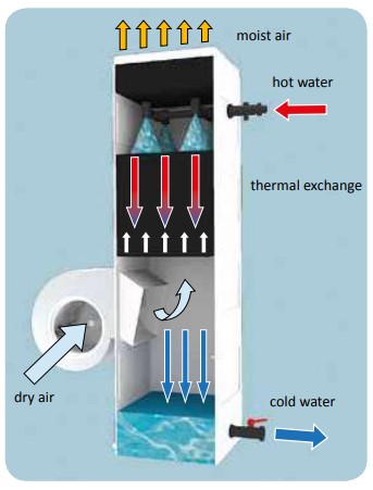
LE PRINCIPE DE FONCTIONNEMENT
Grâce au développement d’une technologie utilisée et renforcée depuis des dizaines d’années dans le secteur industriel, les tours font de la simplicité de construction et de l’efficacité élevée leurs points de force. L’effet réfrigérant est obtenu en pulvérisant l’eau chaude sur une grande superficie d’échange thermique et en soufflant de l’air à contrecourant avec un ventilateur. L’air, qui absorbe l’humidité de l’eau, en provoque l’évaporation partielle (moins de 3% du total) soustrayant ainsi de l’énergie. L’effet qui en résulte est l’abaissement de la température de l’eau restante que l’on recueille dans une cuve interne. Une pompe au nombre de tours variables remet l’eau refroidie dans le circuit et donc dans les machines de production et les vitrines. De plus, étant donné que le principe d’évaporation dépend non seulement de la température de l’air utilisé pour le refroidissement mais également de la capacité de cette dernière à absorber l’eau sous forme de vapeur, la tour peut être installée tant à l’intérieur qu’à l’extérieur de l’établissement, même sous le soleil et sous de fortes températures, maintenant une efficacité très élevée en toutes circonstances .
LES TAILLES ET LES CARACTÉRISTIQUES DE DIMENSIONNEMENTLes tours de refroidissement sont étudiées et conçues pour pouvoir servir toutes les machines présentes habituellement chez un glacier artisanal, permettant la réfrigération du circuit de tous les appareils refroidis à l’eau. Elles sont disponibles en 2 tailles différentes, en fonction de la capacité thermique et, donc, du nombre de machines qui peuvent être refroidies.
LES CARACTÉRISTIQUES TECHNIQUES
Les tours de refroidissement sont étudiées et conçues pour pouvoir servir toutes les machines présentes habituellement chez un glacier artisanal, permettant la réfrigération du circuit de tous les appareils refroidis à l’eau. Elles sont disponibles en 2 tailles différentes, en fonction de la capacité thermique et, donc, du nombre de machines qui peuvent être refroidies.
• Contrôle et régulation: L’écran tactile intégré au cadre permet un accès immédiat à toutes les fonctions
de la machine. Les senseurs de bord relèvent de façon autonome les paramètres de fonctionnement et
effectuent une régulation constante afin de maintenir l’efficacité optimale de l’installation.
• Structure: Toute la machine est réalisée avec des matériaux anticorrosion. La coque en fibre de verre
permet de contenir le poids de la machine, en garantissant ainsi une très haute résistance aux agents
externes et aux conditions météorologiques.
• Échange thermique: Les panneaux en PVC sont structurés pour avoir une grande superficie d’échange
thermique en volumes contenus. Ils sont résistants aux fortes températures et garantissent les
meilleures prestations.
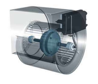
• Ventilateur: Centrifuge à accouplement directe et contrôle électronique de série; l’inverter intégré
permet de moduler la vitesse en fonction de la charge thermique, en limitant au minimum les
consommations et les émissions sonores.
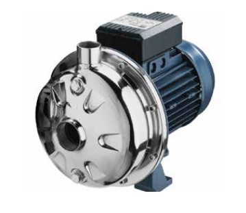
• Pompe: Centrifuge à double stade et avec une roue inox anticorrosion. Elle est commandée par un
inverter à système rétroactif à travers un transducteur de pression, afin de garantir dans toutes les
situations le point de travail optimal de la machine .
• Bypass: L’électrovalve commandée par une sonde thermique dans la cuve permet l’abaissement
brusque de l’eau du circuit à travers l’injection forcée d’eau froide du réseau externe quand c’est
nécessaire. La même valve effectue la purge proportionnelle de l’eau recyclée, en maintenant les
niveaux de calcaire au plus bas.
• Filtres: Le filtre sur la prise du ventilateur limite l’aspiration des impuretés et poussières alimentaires
dans le cas où la machine serait installée à l’intérieur du laboratoire.
• Communication: Le système de contrôle intégré communique à l’opérateur quand effectuer les
contrôles et l’entretien et permet de contacter rapidement le service proposé.
• Inspection et entretien: Les trous d’homme montés sur la coque en fibre de verre permettent un
accès immédiat et simple à toutes les parties internes de la machine, permettant ainsi l’inspection, le
nettoyage et l’entretien en toute simplicité.
L’INSTALLATION INTERNE ET EXTERNE
La tour de refroidissement peut être installée tant à l’intérieur qu’à l’extérieur de l’établissement. L’expulsion de chaleur soustraite aux machines s’effectue grâce à une simple vapeur d’eau à basse température, sans polluer et sans avoir besoin de split externes. L’installation à l’intérieur de l’établissement peut être effectuée en canalisant simplement la machine vers l’extérieur avec un tube en tôle, afin de permettre l’échappement de l’air saturée en sortie .
Au contraire, l’installation peut être effectuée directement à l’extérieur du laboratoire, en laissant la tour à l’air libre et e la positionnant dans une cour, une esplanade ou bien sur le toit. Le seul trou nécessaire est, dans ce cas, celui pour les deux collecteurs principaux d’aller retour entre la tour et les machines du laboratoire. La coque en fibre de verre protège la machine de toutes les intempéries, garantissant ainsi une longévité inégalable. De plus, l’exposition à la lumière du soleil n’a pas d’impact négatif sur la tour qui maintient ses prestations élevées.CRITÈRES DE DIMENSIONNEMENT
La chaleur à dissiper et le choix de la machine
Le calcul de la puissance thermique à dissiper dans un laboratoire de glace artisanale, mesurée en kcal/h, est essentiel pour déterminer de façon juste le modèle de tour d’évaporation plus indiqué. Ce calcul peut se faire de deux façons différentes en fonction des données techniques dont on dispose et selon les machines installées.
Méthode 1 : calcul en fonction des kW installés
Sur les fiches techniques des machines, on note la puissance en kW. Avec celle-ci on obtient l’équivalent thermique
à dissiper. Le résultat obtenu permet d’identifier la « taille » de la tour la plus indiquée.
Exemple
1 machine à glace 4.0 kW
1 pasteurisateur 4.0 kW
1 cuve 3.5 kW
1 vitrine 1.8 kW
------------
TOTAL 12.5 kW
In [kcal/h] 12.5 kW x 1.800 kcal/h/kW = 22.500 [kcal/h] —> Tour la plus indiquée
Méthode 2: calcul en fonction de la consommation d’eau de réseau
En connaissant la consommation horaire d’eau des machines de production, on obtient la portée effective nécessaire
et on peut ainsi identifier la “taille” de la tour la plus indiquée.
Exemple
1 machine à glace 200 l/h
1 pasteurisateur 500 l/h
1 cuve 400 l/h
1 cellule de ref. 200 l/h
1 vitrine 600 l/h
------------
TOTAL 1.900 l/h
In [kcal/h] 1.900 x 3 x 1,5 = 8.550 l/h —> 8.550 x 5°C = 42.750 [kcal/h] (*) —> Tour la plus indiquée
(*) (*) Bien que la température de l’eau en sortie de la tour d’évaporation soit supérieure par rapport à celle que
l’on obtient avec un chiller / groupe frigo, la quantité de chaleur retirée aux machines à refroidir résulte moindre,
puisque la portée d’eau en circulation est 3 fois supérieure.
Notes sur le dimensionnement
La puissance nominale des tours (25.000 et 45.000 kcal/h) fait référence aux conditions opérationnelles suivantes:
T eau en entrée 34 - 35 °C
T eau en sortie 29 - 30 °C
T bulbe humide 24 / 25 / 26 °C (Nord / Centre / Sud)
En cas d’installation à l’intérieur, les conditions opérationnelles sont influencées par les facteurs suivants:
• Aération de l’établissement (peu d’aération = portée de l’air du ventilateur mineure)
• Température et humidité dans un espace clos (T bulbe humide plus élevée = rendu inférieur)
• Longueur du canal d’expulsion d’air (perte majeure de charge = portée de l’air du ventilateur mineure)
SYSTÈME HYDRAULIQUE
DIAMÈTRE MINIMUM NÉCESSAIRE: Les diamètres minimum indiqués sont ceux des collecteurs principaux (aller/
retour). Les “raccord” des tubes principaux aux machines doivent être le plus court possible, avec Ø ¾” (diamètre
interne) et réalisés en tressé métallique (PAS en caoutchouc ou matériel tissé « type machine à laver »).
SÉCURITÉ ET SYSTÈME DE BY-PASS: les deux situations prévues permettent d’opérer avec la tour en fonction ou
bien, en cas de nécessité, d’exclure la tour en continuant à travailler avec l’eau en perte prélevée du réseau publique.
SITUATION NORMALE:
valves V1 et V2 --> ouvertes
valves V3 et V4 --> fermées
EN URGENCE:
valves V1 et V2 --> fermées
valves V3 et V4 --> ouvertes
SYSTEME DE PURGE: la purge périodique de l’eau est effectuée automatiquement à travers le canal de trop-plein.
L’eau expulsée est comptée automatiquement et correspond à la quantité nécessaire pour maintenir le calcaire
dans la machine au plus bas.
Notice : sur demande
Vue éclatée : sur demande